Heat-Powered
Engines (Thermal to Mechanical Conversion)
You lose some energy every time you
either convert it from one form to another, or store it and retrieve
it. For this reason it is best to use energy directly whenever
possible. If there is water to be pumped for instance, the mechanical
energy from wind is best used directly, rather than being converted
first to electricity and then running an electric motor to pump the
water.
Modern electrical generators
(typically alternators) and motors can be quite efficient. They
typically convert between electrical and mechanical energy at rates
better than 90%.
Converting heat energy into
mechanical energy however, is a different matter. A French physicist
named Carnot developed a formula that gives the maximum efficiency
available for a heat engine. Although the steam engine was the target
of his work, his formula works for any form of heat engine: The
maximum efficiency possible from any heat engine can be calculated by
subtracting the exhaust temperature from the maximum temperature, and
dividing this difference by the maximum temperature – the maximum
temperature being degrees above absolute zero. In simple arithmetic
terms this would be written as (tmax-tmin)/tmax.
Compressing gas increases the
temperature, and expanding it cools it. Standard automotive engines
rarely have compression ratios of greater than about 9 to 1. The
temperatures during combustion are thus allowed to expand and cool as
the piston travels downward. The efficiency of such engines is
typically about 20%, although it can exceed 30% under ideal loading
and RPM. Diesel engines however, with compression ratios often
exceeding 20 to 1, can have efficiencies of 40% and higher.
Of
all the various build-it-yourself offerings that have filled books,
magazines, and their ads over the years, none have fascinated me as
much as mechanical energy. I have seen very few articles on the
subject, and fewer still with instructions on how to build your own.
And yet, if a person had a technique for converting THERMAL energy
into mechanical energy, he could:
Produce
his own electricity at his own convenience,
Power
a heat pump for heating his home,
Produce
cooking temperatures from electricity, a specially built heat pump,
or a combination of the two,
Have
more money to spend by choice,
Possibly
even wean himself from the gasoline pump,
Run
air conditioning.
To
summarize, a sustainable energy system could consist of (a) One or
more energy sources designed to produce heat from whatever energy
sources were available in the area, (b) At least one thermal storage
unit (an additional unit might even be designed to store the more
efficient high temperatures, if an appropriate energy source was
available), and ( c )A means of converting the stored thermal energy
into mechanical energy.
Such
technology would be to the development of alternative infrastructures
as the steam engine was to the industrial revolution.
The
reason I emphasize THERMAL to mechanical conversion is because any
form of energy that you might have can be converted into heat. This
would of course include wind power, water power, methane, solar,
firewood, buffalo chips, junk mail, and obsolete utility bills.
Another
reason is for the sake of energy storage. There are few more simple
or economical techniques for storing large amounts of energy than
heating something in an insulated container. Contrast this with the
complexity and environmentally-destructive materials used in battery
technologies. This really came home to me one time as I was reading
about a then high-tech battery that used molten lithium salt. When it
occurred to me to calculate the energy stored in the heat alone, I
found it to exceed the electrical capacity of the battery!
A
further design challenge would be to come up with an engine that
could operate on a relatively low temperature difference. Now I
recognize that a low temperature difference means low efficiency, but
it also increases your options for energy sources.
Consider this
source: I have never lived in a place where there was not a
noticeable difference between day and night time temperatures. Two
thermal storage units could be used to capture this heat and cold for
use in powering an engine.
Here
are some of the thoughts, inputs, and experiments I’ve had
involving thermal-to-mechanical conversion.
1.
I've read
of freon-based turbines that could power air conditioners and
generate electricity, but we are talking kind of high-tech here.
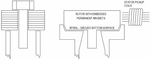
I
have however considered a simple form of steam turbine/generator.
This began as a concept for a pressure release valve, consisting of
a bolt through a stack of washers sitting on the end of a vertical
tube. Any pressure high enough to lift the bolt and washers would be
free to escape. If there were spiral grooves cut in the bottom
washer, and counter-rotating groves in a seat on the end of the
tube, the assembly would spin. If you hadn’t guessed, this
assembly could become the rotor of a small generator with a built-in
pressure release.
I
read of two sealed cylinders half filled with water connected by
pipe that ran through a water motor. The air in one cylinder was
expanded by a spray of hot water while the air in the other was
being shrunk by a cold shower, forcing water to run through the pipe
and motor, as it traveled from one cylinder to the other. Next, the
hot cylinder got a cold shower while the cool cylinder got a hot
shower, sending the water racing the other direction. The motor was
actually connected through some extra plumbing involving check
valves, to keep it spinning the same direction with each change of
direction. Water was recycled in the system to be sent to the cooler
or the heater. This was a very creative and practical system that
was apparently too dangerous to big business to allow more than a
brief accidental public exposure.
4.
I built a
low tech steam engine -- functional, but needs work.
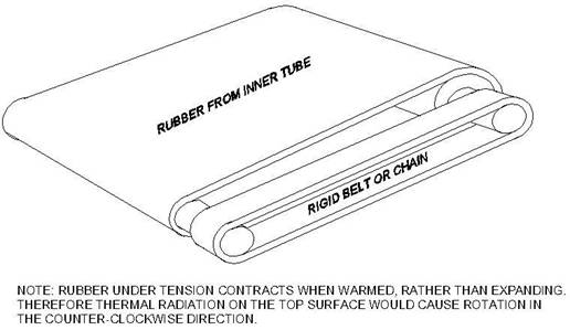
A
rubber band
I
used super glue to glue thin strips of aluminum foil and hard thin
plastic together, and sprayed the resulting bi-material strip black.
You get a lot of bend when you expose it to radiant heat. I even
made a crude flower from this product, which would open up when you
brought it next to the woodstove. Approximately speaking, plastics
expand and contract with heat about ten times more than metals do,
for the same temperature change. This could be an interesting way to
get the sunshine to do something mechanical directly. Like most
things, I discovered this the hard way. I had built a solar panel
with a flat plastic cover, and the whole thing tried to pretzel when
it warmed up.
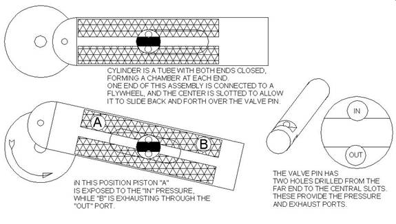
Concept
steam engine with two-cylinders and two moving parts. The cylinders
are the closed ends of a single piece of tubing, slotted to clear
the valve pin. One end of the tube is fitted with a connection
to the flywheel. The flywheel rocks the cylinder/ piston assembly
back-and-forth, alternately exposing pistons to the pressure and
exhaust channels in the valve shaft.
a. Pistons
'A' and 'B' are a single piece,
b. They
inhale and exhale through tubes in the valve pin
c. They
pivot at the center of a stationary valve pin
We
need more experimenters who do not hide what they discover and prove,
but give freely of the creativity and gifts that God has given them.
Stand on my shoulders. We desperately need some appropriate
technology products to fill this need. Don't tell me about perpetual
motion, mysterious magnetic things, motors that run generators that
run motors, or things that go "Tesla" in the dark. If you
actually build something that produces a power output, and you can
show me a working model, and if other people can build it and make it
work, and if it requires nothing that you cannot find in a small
town, then you will have a potential contribution.
Check-Valve-Engine
Ok,
so I have neither made one, seen one, or even heard of one, but this
next one is still an interesting idea. I must allow that somebody
else somewhere in history may have already invented it, and that I’m
merely laying claim to somebody else’s brilliant or stupid idea.
I was contemplating ideas
for the simplest possible positive displacement engine, and this is
what I came up with. This engine consists of a piston and cylinder,
two check valves, a heat sink to cool the air, and a heat source to
heat it. While referencing the drawing below, consider the following:
1. When
the piston travels upwards air tries to enter both the source and
sink.
2. The
source doesn’t want any however because as it tries to enter it
expands and is forced back out.
When
it enters the cool side however (the heat sink), it begins to
contract and really sucks, while check #2 keeps any of the hot air
from getting sucked over to the sink.
As
the piston begins to withdraw, cool air is drawn through the heat
source and begins to expand, but check #1 does not allow this
pressure to return through the heat sink. This directs all the
pressure
to the face of the piston via the heat source.
Passive
Solar Air Compressor
Squarely
in the “random idea” camp, consider a passive solar-powered air
compressor. Place a series of tubular tanks side-by side in an
east-west line. They are connected to each other by check-valves that
allow air to flow only from west to east.
The
west-most tank also has a check valve that allows outside air to
enter, but does not let it escape – its air can only escape into
the tank immediately to its east. The east-most tank has a fitting to
allow the use of compressed air.
Above
this row is a shade with a slit in it that allows the sun to heat one
tank at a time as the sun progresses across the sky. As each tank
heats it dumps its expanding air into the tank east of it, and then
cools to receive air from the tank to its west.
The
pressure would increase in each tank in sequence from west to east.
This arrangement would be a little more effective if the tanks were
placed in a semicircle where each one was the same distance from the
slit. If the slit were covered by a fresnel lens, heat could be
concentrated, and the tanks could all be in the same plane.
A
Jet Engine In My Living Room
This
one was almost tragic. A major portion of our heating in Colorado was
provided by a high-efficiency woodstove in the living room. It was
pleasant to have a nice warm room to hide in, but it did little for
our bedroom or the rest of the downstairs rooms.
There
were some existing ducts I could have tapped into, and distributed
heat with the aid of a blower, but that would have been too easy –
and besides, how would that be of any use during a power (or
economic) failure?
I
reasoned that the stove itself was a great source of energy, and that
I could convert some of it into mechanical energy to drive a blower.
I was initially considering a low-temperature-difference turbine, but
figured the best reliability would be to have no moving parts –
don’t laugh, ram-jets do it, if you happen to be current on
hyper-sonic fluid dynamics.
Well,
I came up with a configuration that I thought might work (without the
benefit of hyper-sonic fluid dynamics), and being a little low on
cash I fabricated it out of used flue pipe. My family has had to put
up with a lot, and on its maiden voyage the “used” part of the
pipe began to smoke.
Suddenly
there was a loud roar accompanied by a scream from my wife as a three
foot spear of orange-violet flame was blasting out of the device
about 3-1/2 feet above the floor. After a few seconds the flame
ceased, but the experiment was still red hot and continued to spew a
5” diameter blast of scorching air for a few more
seconds.Apparently the thin crust of creosote in the pipe had ignited
and provided the jet fuel.
Looking
on the bright side:
· No
one was hurt.
· The
smoking stopped.
· The
house was a little warmer.
· The
kids were very well behaved for awhile.
· Something
about the configuration worked
· I
haven’t messed with it since.
In
the early nineteenth century a young Scottish minister named Robert
Stirling was concerned about the number of people being killed or
maimed by exploding steam engines. So he invented an engine that
could not explode, and his engines are still the world’s most
efficient engines ever developed.
Referencing
the drawing below, the energy is obtained from the temperature
difference between the COLD SURFACE and the HOT SURFACE. These two
surfaces are separated by a cylinder of an insulating material so
that the two surfaces will not cancel each other out by conduction.
The
DISPALCER PISTON is also of an insulating material, and fits loosely
so that air can move freely around its outside edges. It is shown
here next to the COLD SURFACE. Since the air itself is in this case
in contact with the hot surface it is in its expanded state and the
power piston is at the top of its stroke.
In
this next drawing the displacer piston has been pushed downward.
Since the air was able to flow freely around its perimeter, it took
no significant energy to move it.
The
air however, has now been forced into contact with the cold surface
and has contracted. This has sucked air through the hole, pulling the
power piston to the bottom of its cylinder.
Presumably
our young minister became bored with moving the displacer piston in
and out just so he could watch the power piston jump around, so he
connected them both to the same crank shaft, with a flywheel to keep
the motion smooth.
By
having the displacer piston lead the power piston by 90 degrees, the
pressure in the system was always changing just ahead of the power
piston. By the time the power piston was at top dead center because
the air had just been heated, for instance, the displacer piston was
already halfway back down, beginning to create a vacuum. In this way
the power piston was always chasing the displacer piston but never
quite catching up with it. I am sure we all have situations in our
own lives that can relate to this.
Stirling
had yet another trick: If you enlarged the displacer piston so the
air could not so easily slip past it, and then drilled holes in it so
that air could flow through it, you could force the air past
conductive material that would store its heat or cool. In this way,
hot air on its way to the cool side would leave some of its heat in
the piston itself, and pick it up on its way back to the hot side.
This clever REGENERATOR component is what makes a true Stirling
engine so efficient.
There
are many clever variations of Stirling engines suitable to various
applications, but they all involve moving air between hot and cold
surfaces and continually changing pressure on a power piston. True
Stirlings also include some form of regenerator.
This
category of engine is the most promising technology for sustainable
energy for several reasons:
· It
is the omnivore of the engine world. Unlike internal combustion
engines, it doesn’t care what you feed it – as long as it’s
hot.
· It
can be configured to operate on low temperature differences. I have
seen model Stirling engines animated by setting them on a cup of hot
water (I suppose that would animate most of us), and it would change
directions when my friend would move it over to a cup of ice water.
· They
can’t explode. They don’t even have steam to hiss and chuff out
of whatever.
· Unlike
internal combustion engines, they are not noisy; all the motions are
smooth and explosion free.
There
is yet another important feature of these marvelous machines –
consider: If you were to apply rotation to this device from some
external source, the power piston would compress air while it is next
to the normally cold side, and evacuate it while the air while it is
next to the normally hot side. Depending upon which direction you
turned it, one side would produce heat, and the other side would
cool.
I
am saying that a Stirling engine may be used as a heat pump to
produce both hot and cold surfaces! Consider a scenario on a hot day
where concentrated solar energy is efficiently running a large
Stirling engine. This engine is driving a smaller engine which is
cooling a living space (or a keg). No point in wasting the heat
produced, so it is either recycled to contribute to the solar heat,
or stored for later use.
The
thing that disappoints me most about Stirling engines is the fact
that I’ve never built one, but lots of people have. The internet
has enough sites and Stirling engine drawings and information to
thoroughly confuse anybody.
If
I can ever catch up with my to-do list – if I can just catch that
displacer piston – I too will have one to share.
There are three things that must be
controlled to make an efficient Stirling engine:
All forms of thermal shorts
Transfer of heat to and from the
internal air
All forms of friction.
The thermal shorts can be minimized
by using insulating materials in the displacer piston and cylinder.
Surface to air heat transfer is of course related to the amount of
surface the air contacts. For this reason the displacer cylinder is
typically short and wide to maximize the hot and cold surfaces.
The rate of energy derived will
naturally increase with the rpm. When you have a broad flat displacer
piston, the mechanical stresses could soon become extreme.
The greatest source of friction is
likely to be along the sides of the power piston. Other sources would
include all rotating and shaft sliding bearings, and any mechanical
linkage involved in connecting the engine to actual work. A third
category could involve the movement of the air itself as it is
shuttled back and forth between the hot and cold surfaces.
Machined parts are expensive, for,
so initial experimenting I cast a plastic piston in the actual
cylinder. An automotive filler putty (AKA “Bondo” ® ) would
probably work, as well as other forms epoxy.
When the piston is cast, it must
include either a connecting rod, or some means of attaching one. For
a very light-weight experiment, a flexible wire might be enough to
serve as the rod itself.
To allow some clearance and
lubrication first apply a layer of grease to the inside of the
cylinder (with a Q-tip), and then stick a layer of graphite to it
(Q-tip also) to provide lubrication. The grease is intended to allow
the piston to be released. It is then wiped out and replaced by a
light machine oil.
As a group, plastics expand roughly
ten times as fast with changes in temperature as metals do, so a
plasticpiston in a metal cylinder might get a little snug as
temperatures increase. One way to minimize this would be to make the
core of the piston out of metal, and just cast the outermost layer
with plastic.
Another thermal consideration would
be that plastics have a limited temperature range, so if you have a
high-temperature heat source, plastics may be impractical.
Just how much friction can be
tolerated, and how much pressure will be available to move the
piston? The atmospheric pressure at sea level is about 14.7 lbs per
sq. in. of surface. If we take the value from the Carnot column in
the table below, and multiply it by 14.7, we get the maximum number
of pounds per square inch change available from the respective
temperature change.
Referencing the first line of the
table below (Tmax = 212, and Tmin = 100), the Carnot value is 0.167.
If we multiply this times 14.7, we have a change in pressure of 2.45
psi. Our piston with a bore diameter of 1.5” has a surface area of
1.77 square inches. This gives us a total maximum pressure on the
piston of: 1.77 times 2.45 = 4.33lbs.
Pressure does add up quickly with
area. When we check of the total pressure against the top and bottom
hot and cold surfaces we might be surprised. A 6” diameter circle
has an area of 28.3 square inches. 28.3 times our pressure of 2.45
lbs gives us a total of almost 70 lbs! So we need to be careful of
this innocent toy.
The table below provides
calculations based upon what I think I understand at this point. When
a prototype is developed to where actual measurements can be made and
confirmed, this information will be modified, confirmed, or laughed
at. This table relates only to the potential energy before the
various forms of inefficiency are considered. At best, I wouldn’t
expect a real world performance of more than half the power
anticipated by the table.
For those who want to try it,
consider the table and the comments that follow.
The table begins with the desired
power in Watts, followed by translations into horsepower and ft.
lbs. per second.
Tmax and Tmin represent the hot
and cold gas temperatures respectively.
Dimensions of the displacer and
power pistons are next.
Cycles/sec are cycles per second
The Carnot efficiency is the
highest efficiency achievable from a perfect engine – no matter
what you do. This is equal to the (Tmax-Tmin) divided by the Tmax.
The catch here, is that all
temperatures are measured from
absolute zero.
“Calories” is the amount of
heat stored or released in the air during a single transition of the
displacer piston.
The normal headings are the
“givens” in this table, and the bold headings are values
calculated from the givens.
Displacer and Power refer to the
displacer piston and the power piston respectively.
|
ALL
DIMENSTIONS ARE IN INCHES
|
|
|
|
|
|
|
|
|
|
|
|
ft.lb/sec
|
|
Displacer
|
Power
|
cycles/
|
|
calories/
|
|
Watts
|
hp
|
sec
|
Tmax
|
Tmin
|
dia.
|
stroke
|
volume
|
bore
|
stroke
|
sec
|
Carnot
|
cycle
|
|
10.0
|
0.013
|
7.4
|
212
|
100
|
6
|
1.0
|
28.0
|
1.50
|
2.64
|
5
|
0.167
|
5.7
|
|
50.0
|
0.067
|
36.9
|
212
|
100
|
10
|
2.2
|
175.0
|
3.00
|
4.13
|
4
|
0.167
|
35.8
|
|
200.0
|
0.268
|
147.5
|
212
|
100
|
18
|
3.7
|
933.4
|
5.0
|
7.9
|
3
|
0.167
|
191.1
|
|
500.0
|
0.670
|
368.7
|
212
|
100
|
24
|
7.7
|
3500.2
|
6.0
|
20.6
|
2
|
0.167
|
716.4
|
|
1000.0
|
1.340
|
737.5
|
212
|
100
|
32
|
8.7
|
7000.4
|
8.0
|
23.2
|
2
|
0.167
|
1432.9
|
|
5000.0
|
6.702
|
3687.3
|
212
|
100
|
60
|
12.4
|
35002.0
|
15.0
|
33.0
|
2
|
0.167
|
7164.5
|
|
20.0
|
0.027
|
14.7
|
140
|
32
|
6
|
1.8
|
49.8
|
1.5
|
5.1
|
5
|
0.180
|
10.6
|
|
50.0
|
0.067
|
36.9
|
212
|
32
|
8
|
0.8
|
42.2
|
2.0
|
3.6
|
4
|
0.268
|
22.3
|
|
200.0
|
0.268
|
147.5
|
212
|
32
|
12
|
2.0
|
224.9
|
3.0
|
8.5
|
3
|
0.268
|
118.9
|
|
500.0
|
0.670
|
368.7
|
212
|
32
|
16
|
4.2
|
843.2
|
4.0
|
18.0
|
2
|
0.268
|
445.8
|
|
1000.0
|
1.340
|
737.5
|
212
|
32
|
24
|
3.7
|
1686.4
|
6.0
|
16.0
|
2
|
0.268
|
891.6
|
|
5000.0
|
6.702
|
3687.3
|
212
|
32
|
36
|
8.3
|
8432.0
|
9.0
|
35.5
|
2
|
0.268
|
4457.9
|
|
100.0
|
0.134
|
73.7
|
350
|
100
|
6
|
1.3
|
36.6
|
1.5
|
6.4
|
5
|
0.309
|
31.0
|
|
200.0
|
0.268
|
147.5
|
350
|
100
|
8
|
1.8
|
91.5
|
2.0
|
9.0
|
4
|
0.309
|
77.4
|
|
500.0
|
0.670
|
368.7
|
350
|
100
|
12
|
2.7
|
304.8
|
3.0
|
13.3
|
3
|
0.309
|
257.9
|
|
1000.0
|
1.340
|
737.5
|
350
|
100
|
18
|
3.6
|
914.5
|
4.5
|
17.7
|
2
|
0.309
|
773.8
|
|
1000.0
|
1.340
|
737.5
|
350
|
100
|
18
|
3.6
|
914.5
|
4.5
|
17.7
|
2
|
0.309
|
773.8
|
|
5000.0
|
6.702
|
3687.3
|
350
|
100
|
30
|
6.5
|
4572.6
|
7.5
|
31.9
|
2
|
0.309
|
3868.8
|
|
100.0
|
0.134
|
73.7
|
500
|
100
|
6
|
1.1
|
31.4
|
1.5
|
7.4
|
2
|
0.417
|
57.3
|
|
200.0
|
0.268
|
147.5
|
500
|
100
|
8
|
1.2
|
62.7
|
2.0
|
8.3
|
2
|
0.417
|
114.6
|
|
500.0
|
0.670
|
368.7
|
500
|
100
|
12
|
2.8
|
313.6
|
3.0
|
18.5
|
1
|
0.417
|
573.2
|
|
1000.0
|
1.340
|
737.5
|
500
|
100
|
18
|
4.9
|
1254.5
|
4.5
|
32.9
|
0.5
|
0.417
|
2292.6
|
|
1000.0
|
1.340
|
737.5
|
500
|
100
|
24
|
2.8
|
1254.5
|
6.0
|
18.5
|
0.5
|
0.417
|
2292.6
|
|
5000.0
|
6.702
|
3687.3
|
500
|
100
|
30
|
4.4
|
3136.2
|
7.5
|
29.6
|
1
|
0.417
|
5731.6
|
|
100.0
|
0.134
|
73.7
|
800
|
100
|
3
|
0.7
|
5.0
|
0.8
|
6.3
|
4
|
0.556
|
21.5
|
|
200.0
|
0.268
|
147.5
|
800
|
100
|
4
|
1.1
|
13.4
|
1.0
|
9.5
|
3
|
0.556
|
57.3
|
|
500.0
|
0.670
|
368.7
|
800
|
100
|
8
|
2.0
|
100.8
|
2.0
|
17.8
|
1
|
0.556
|
429.9
|
|
1000.0
|
1.340
|
737.5
|
800
|
100
|
8
|
2.0
|
100.8
|
2.0
|
17.8
|
2
|
0.556
|
429.9
|
|
1000.0
|
1.340
|
737.5
|
800
|
100
|
12
|
1.8
|
201.6
|
3.0
|
15.8
|
1
|
0.556
|
859.7
|
|
5000.0
|
6.702
|
3687.3
|
800
|
100
|
24
|
4.5
|
2016.1
|
6.0
|
39.6
|
0.5
|
0.556
|
8597.4
|
|
|
|
|
|
|
|
|
|
|
|
|
|
|
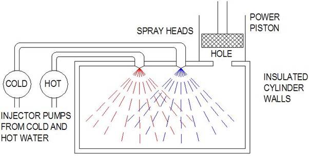
One
other wild idea before leaving this subject: If you are using a
system based upon hot and cold water for energy sources, consider
replacing the displacer piston with a chamber as shown below. The
chamber is heated and cooled by sprays of alternating hot and cold
water, which is recycled. The injector pumps would serve the dual
purpose of spraying the chamber and circulating the water, and could
be either coupled mechanically or driven by solenoids. If driven
electrically by solenoids they could be timed to the top and bottom
dead centers of the power piston (as opposed to the 90-degree lead of
mechanically coupled systems), and thereby increase the efficiency.
The internet has lots of videos and
discussions related to Stirling engines. If you're serious about
this, there is plenty of research that can be done.