Solar Heated Water
A flat black surface directly facing the sun can absorb up to about 300 BTU per hour for every square foot (One BTU will heat one pound of water one degree Fahrenheit).
One gallon of water weighs 8.345 lbs. This square foot would heat one gallon of water by 300 BTU/8.345 lbs = 36 deg. F.
One cubic foot of water weighs 62.4 lbs. This would heat one cubic foot of water by 300 BTU/62.4 lbs = 4.8 deg. F.
Such is the potential energy available, but there is a lot more to the story that may not allow you to capture all of it.
· As the sun crosses the sky, it will spend most of the day hitting the surface at an angle.
· As the temperature of the water increases, heat will be reradiated back towards the sky. This loss will increase with the fourth power of the absolute temperature
· Moving air will carry some of the heat away.
· Dust on the surface could reflect some of the energy.
· There would be some loss as you move the heated water down to where you want it.
All-in-all, capturing two-thirds of the optimum figure is still a bargain. Half-inch black plastic tubing is one of the cheapest forms of tubing you can buy, and it can be plumbed with simple tools.
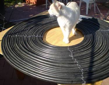
I heated a plastic pool 14’ dia. X 3’ deep (460 cu.ft) using two coils of 1/2” black plastic tubing about 7’ in diameter. They were secured to each other and to pre-punched strips of galvanized steel using black nylon tie straps.
This arrangement worked OK, but there were enough problems that I intend to do it differently next year.
1. The flow rate was too constrictive.
a. By the time the water had flowed all the way through one of the tubes, it was pretty hot. This caused much greater losses to the environment.
b. It made the pump work harder.
2. They were too heavy and unwieldy to move.
3. The nylon ties deteriorated in the sunlight and began to break.
The answer to the first two problems is to go with multiple smaller units, rather than a couple of large ones. The plumbing will manifold these together, so that water will flow in parallel circuits, rather than in a serial sequence. Another improvement might be to use larger-diameter tubing.
18-gauge wire will replace the nylon ties. This could be rougher on the plastic, so it must be done carefully.
The proposed design would consist of 4’ diameter coils with 18” diameter holes in the center (12” might work, but I don’t want to count on bending the plastic tubing too tightly).
This would give us about 10.8 square feet per panel, with a peak possible output of 3024 BTU per hour. This is just-under one kilowatt-hour of energy.
The 4’ diameter would allow us to mount everything on a standard piece of exterior plywood. By drilling holes at 1” intervals radiating outwards in 4 directions, wires could be run through from the back side to tie down the tubing.
This 1” spacing will leave small gaps between the tubes, but since the sun will be striking fixed panels at an angle most of the time anyway, this will result in a greater use of the absorbing surface of the tubing. Also, the sun light absorbed between the tubes has little place to go besides into the tubes themselves.
If the holes were sequenced diagonally, instead of at right angles to the sides, you could get almost another two feet of diameter, but you’d be reverting to some of the size problems mentioned above. Also, the outer wraps of tubing would be virtually unsupported. It might be practical to extend just 9” in each direction in this manner however, giving a total diameter of 5’ 6”. This by the way would provide 22 sq.ft. and 6,590 BTU – double that of the 4’ diameter.
You could mount two coils on each sheet, but I plan to cut each sheet in half so that each coil would be more portable. This would serve well if you wanted to take a coil with you to provide hot water while camping out. Another benefit is that you can stack the half-sheets while drilling and do all sixty-some holes in both pieces at once. You could drill holes in the corners so you could wire them together for structural integrity once in position on the roof. Half-sheets would also be needed if diagonal placement of the holes was desired.
For plywood, I would suggest 3/8” exterior sheeting that has been heavily sealed and painted to resist the weather. I considered spacing them off the roof with 2X4’s so that plumbing could be underneath them, but I think I’ll spare the extra weight and bulk and stay with ugly instead.
I’ve also considered cutting out hexagonal pieces of plywood, but the point-to-point distance of the hexagons would require about 56”, and would only allow one coil per 4X8 sheet.
The manifold connections should branch off pipes of significantly greater diameter than that of the tubing. This is so that the velocity of the water in these tubes will not cause uneven rates of flow in the separate panels.
If you have panels at different vertical levels, mount any manifolds at the highest level of the highest panels. This would guarantee even pressure at all ports.
UPDATE:
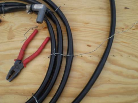
My plywood-mounted version is shown here. The wire is threaded through the plywood to secure each wrap of ¾” black plastic tubing at several points around the torus. While doing two or three of these I was increasingly annoyed by how labor-intensive it was, and began to doubt that there is any value in the gaps between them. This stuff is much cheaper than the time it takes to wire it down, so I moved on to another version.
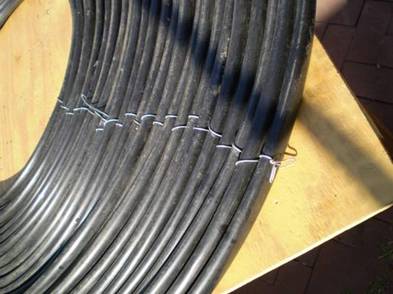
In this case, the plywood is used only as a workbench, and is not actually attached to tubing. The tubing is connected only to itself as the wires are simply woven back and forth to capture each winding in several places. Additional sections of wire lacing might be added to the outer turns to give more stability as the initial tie rays become farther apart. In practice, this proved to be quite a bit easier than securing it to plywood.
VERY IMPORTANT!! There are mistakes you cannot afford to make even once in life, and having a loose end of #18 galvanized wire penetrate your eyeball is one of them.
In lacing this tubing you will continually have loose ends traveling in unpredictable directions. Notice in the second photo how the ends have been bent over. This in itself is not a guarantee, but it is a precautionary discipline that must be maintained on all loose ends whenever you are handling wire.
Convection Solar
I have heard of solar hot water systems that used no pump at all, but have not actually succeeded in building one myself.
The water is moved through the tubing by convection, which is based upon the fact that hot fluid is lighter than cold fluid, and therefore tends to rise.
For such a flow to take place the storage tank must be elevated well above the collector, and must have connections near both the top and bottom of the tank. The collector coil should have at least a little slope to it.
It is crucial that there be no air in the pipe, and that the water level in the tank consistently remains above the entry of upper pipe. The hottest water will be taken from the upper edge of the collector and fed into the top of the tank, while the coolest water will settle to the bottom where it is returned to the input side of the collector. If you want to actually use this hot water, you're going to need to put a "T" in the pipe leaving the bottom of the bucket. If you want more than one shower you may need a bigger bucket -- might I suggest a half of a 55 gallon drum that was not used for pesticides? Be careful here, a 55 gallon drum full of water will weight over 400 lbs, and would be an annoying visitor to suddenly drop in on anybody's shower.
Although I have some confidence in the solar collector technology I have just described, I want to repeat that I have not actually built a convection system myself. So, until then, I'll leave it to you to make all the mistakes.